Why Choose a Press Brake for Metal Fabrication?
Why Choose a Press Brake for Metal Fabrication?
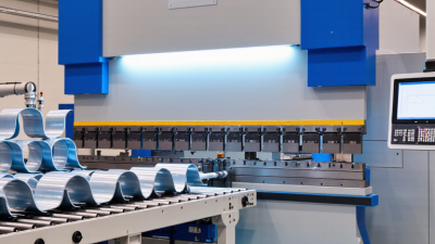
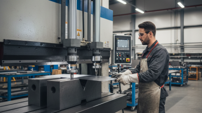
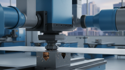
Metal fabrication demands accuracy, repeatability, and controlled production costs. A Press Brake addresses these needs by bending sheet metal with measured force and consistent tooling. Operators can form brackets, enclosures, channels, and structural panels from one controlled workstation. The result is a cleaner bend line, fewer rejected parts, and more predictable assembly.
Industry research supports this direction. Grand View Research identifies automation, precision equipment, and production efficiency as important drivers in the global metal fabrication equipment market. Deloitte’s 2024 Manufacturing Industry Outlook also highlights manufacturers’ continuing investment in automation, digital workflows, and labor productivity. These findings matter on the shop floor. A modern Press Brake can store programs, guide setup decisions, and repeat complex angles across multiple batches. Less guesswork helps.
Still, the choice is not automatically right. A machine may look impressive and remain poorly matched to the work. Material thickness, bend length, tonnage, tooling access, operator skill, and expected batch volume must be reviewed carefully. Research and Markets’ press brake industry analyses emphasize automation and flexible manufacturing, but flexibility requires disciplined planning. That part is easy to underestimate.
Consider a stainless-steel cabinet panel. A precise back gauge positions each blank, while the tooling forms several bends without repeated manual marking. The panel leaves the machine ready for inspection, not rescue. Energy use, maintenance access, software support, and training also influence the real return on investment. In practice, the best Press Brake is not always the fastest model. It is the machine that reliably connects design data, operator judgment, and finished-part quality.
Press Brake Fundamentals: Tonnage, Bed Length, and Bending Capacity
Why Choose a Press Brake for Metal Fabrication?
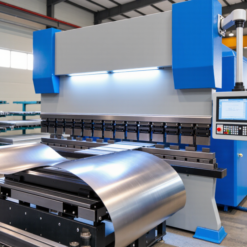
Press brake performance depends on three practical measurements:
tonnage, bed length, and bending capacity.
Tonnage is the force required to form metal without excessive deflection. It changes with material strength, thickness, bend length, and die opening. A 6 mm steel plate needs far more force than a thin aluminum sheet. The same applies to longer bends.
Bed length defines the maximum working width. A long bed suits large panels, but it does not automatically provide greater forming force. Tonnage is distributed across the bend line. Uneven loading can damage tooling or distort the frame.
I have seen operators focus on overall bed length while overlooking concentrated loads near one side. That mistake is expensive.
Bending capacity includes more than maximum thickness. It also covers flange depth, inside radius, material type, and the chosen bending method. Air bending offers flexibility, while bottoming requires more controlled force and tooling.
Check the machine’s rated tonnage across the required bend length, not only its headline capacity. Leave a sensible margin for material variation and repeated production. More capacity is not always better.
An oversized machine may waste energy, floor space, and setup time. A smaller press brake can perform well when its limits are honestly understood. Sometimes, the specification sheet is too optimistic. Verify it with a sample bend.
Step 1: Select a V-Die Opening of 6–8 Times the Sheet Thickness
Why Choose a Press Brake for Metal Fabrication?
Step 1: Select a V-Die Opening of 6–8 Times the Sheet Thickness
A press brake begins with one practical decision: the V-die opening. For air bending, a common workshop guideline is six to eight times the sheet thickness. This range supports a larger inside radius and reduces excessive forming force. For a 2 mm mild-steel sheet, a 12–16 mm opening is a sensible starting point. It is not a law.
The ASM Handbook, Volume 14B, identifies die geometry as a major factor in bending force, springback, and surface damage. The Machinery’s Handbook, 31st Edition, also relates bending force to material strength, thickness, bend length, and die width. Wider openings usually reduce tonnage, but they can increase springback and reduce angle consistency. Narrow openings may create sharper bends, yet they raise force and marking risks. Check the material grade, rolling direction, bend radius, and machine capacity before production. Measure the first part. Then adjust.
In practice, I would test a short sample before loading a full sheet. A 3 mm high-strength sheet may need more force than a thicker mild-steel sheet. That detail is easy to overlook. The 6–8-times rule works well as a starting point, but it still needs judgment, calculation, and inspection.
Why Choose a Press Brake for Metal Fabrication? - Step 1: Select a V-Die Opening of 6–8 Times the Sheet Thickness
| Sheet Thickness |
Recommended V-Die Opening
(6–8 × Thickness) |
Typical Inside Bend Radius
(Air Bending Estimate) |
Indicative Minimum Flange
(Approximately 0.67 × V) |
Common Fabrication Applications |
| 1.0 mm |
6–8 mm |
Approximately 1.0–1.3 mm |
Approximately 4.0–5.4 mm |
Light enclosures, covers, brackets |
| 1.5 mm |
9–12 mm |
Approximately 1.5–1.9 mm |
Approximately 6.0–8.0 mm |
Cabinet panels, equipment guards |
| 2.0 mm |
12–16 mm |
Approximately 1.9–2.6 mm |
Approximately 8.0–10.7 mm |
Frames, trays, machine panels |
| 3.0 mm |
18–24 mm |
Approximately 2.9–3.8 mm |
Approximately 12.0–16.1 mm |
Structural brackets, bases, support parts |
| 4.0 mm |
24–32 mm |
Approximately 3.8–5.1 mm |
Approximately 16.1–21.4 mm |
Heavy-duty frames, mounting channels |
| 6.0 mm |
36–48 mm |
Approximately 5.8–7.7 mm |
Approximately 24.1–32.2 mm |
Heavy brackets, structural components |
Selection Notes:
- The 6–8 times guideline is a practical starting range for air bending and should be confirmed with the tooling supplier and machine manufacturer.
- A larger V-die opening generally produces a larger inside bend radius and requires less forming force, but it may increase the minimum practical flange length.
- The actual bend radius depends on material grade, tensile strength, rolling direction, tooling condition, bend angle, and press-brake setup.
- Always verify the selected die opening against the punch tip, material width, required angle, allowable tonnage, and the machine’s operating limits.
Step 2: Match CNC Control with ±0.01 mm Positioning Repeatability
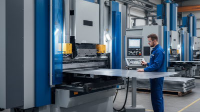
A press brake earns its place when its CNC control turns repeatable motion into consistent bends. A ±0.01 mm positioning repeatability target sounds precise, but it describes axis movement, not finished-part accuracy. Sheet thickness, grain direction, tooling wear, and frame deflection still influence the bend angle.
ISO 230-2 provides a recognized method for evaluating machine-tool positioning accuracy and repeatability. Use it during acceptance testing, not only during a sales demonstration. Ask for measured results across the working length, under realistic load conditions. A control should also display commanded and actual positions. That detail helps technicians find backlash, thermal drift, or calibration errors.
The 2024 State of Smart Manufacturing report surveyed 1,560 manufacturers and found that 95% planned to use artificial intelligence or machine learning within five years. That trend makes data-ready CNC controls more valuable. However, software cannot correct poor setup discipline. A practical operator still checks the first bend with a calibrated angle gauge and records the correction. Real shops are messier. A machine may repeat ±0.01 mm in a cool morning test, then shift after hours of production. I would question any specification without temperature data, test conditions, and a documented verification method. The best control connects repeatability with traceable measurements, usable diagnostics, and quick correction at the press brake.
Why Choose a Press Brake for Metal Fabrication?
Step 2: Match CNC Control with ±0.01 mm Positioning Repeatability
Representative engineering targets show how tighter backgauge positioning repeatability supports progressively more demanding sheet-metal work. A CNC control specified at ±0.01 mm helps reduce dimensional variation between repeated bends, improving consistency for precision components and multi-part production.
Step 3: Compare Hydraulic and Electric Drives by Energy Consumption
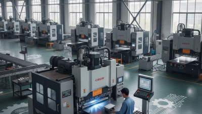
Choosing a press brake requires more than comparing tonnage and bending length. Energy consumption deserves equal attention. Hydraulic drives use a pump, valves, oil, and a motor to create pressure. A fixed-speed pump may continue running during pauses, producing heat and wasting power. Electric servo drives use controlled motors that draw energy mainly during movement. They can remain nearly idle between bends.
The U.S. Department of Energy’s Motor Systems Market Assessment reports that motor-driven systems consume about 53% of industrial electricity. Its motor-system guidance also warns that savings depend heavily on load patterns and operating hours. The U.S. Department of Energy’s Improving Motor and Drive System Performance sourcebook recommends measuring real operating conditions before predicting savings. That matters in fabrication shops. A machine bending short flanges may spend more time waiting than forming metal. Electric drives can then show a strong advantage. Hydraulic systems with variable-speed pumps may narrow the gap, especially under heavy, continuous production.
Measure before deciding. Log motor power, standby time, cycle frequency, and monthly production. Compare kilowatt-hours per finished part, not only rated motor size. A practical test should include oil temperature and maintenance time. The comparison is not perfectly clean. Operator habits, material thickness, and idle settings can distort results. My own preference is to trust logged data over sales estimates. Yet even a careful audit can miss seasonal workloads, so the result deserves review after several months.
Step 4: Verify Safeguarding Against ISO 12100 and EN 12622 Requirements
Why Choose a Press Brake for Metal Fabrication?
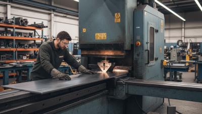
A press brake delivers repeatable bends, but productivity should never outrank safeguarding. During commissioning, operators should inspect the die area, rear gauge, foot pedal, and access points. ISO 12100 requires a documented risk assessment covering intended use, foreseeable misuse, and residual risks. EN 12622 adds press-brake safety expectations, including guarding, stopping performance, controls, and access prevention.
Industry data shows why this review matters. The UK Health and Safety Executive reported 1.7 million work-related ill-health cases in 2023/24, including 543,000 musculoskeletal cases. Repetitive loading, awkward sheet handling, and unexpected movement can create serious exposure. A capable fabricator should test the machine with real tooling, sheet thicknesses, and normal production reach distances. A paper checklist alone may miss practical hazards. That deserves honest reflection.
Tips: Verify safety distances with measurements, not estimates. Test emergency stops, interlocks, and light curtains under realistic conditions. Record stopping-time results and corrective actions. Ask for validation evidence, but do not treat documentation as proof of safe installation. Confirm the current national adoption of ISO 12100 and EN 12622 before acceptance. A trained operator should understand muted protection, restart prevention, and safe setup procedures.